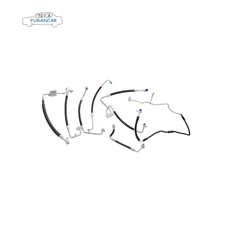
Auto air conditioning pipework
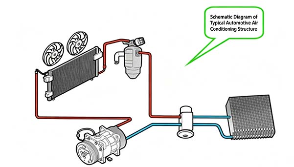
Air conditioning piping connects the four major components of the system—the compressor, condenser, evaporator and expansion valve—to form a closed system, within which the refrigerant is stored or circulates. When the air conditioning system is in operation, the refrigerant circulates continuously, exchanging heat with the outside environment to achieve the cooling function. To ensure the refrigerant transfers heat smoothly and efficiently, the routing of the pipework must be well-designed, facilitating both assembly and disassembly, whilst also being easy to manufacture and cost-effective.
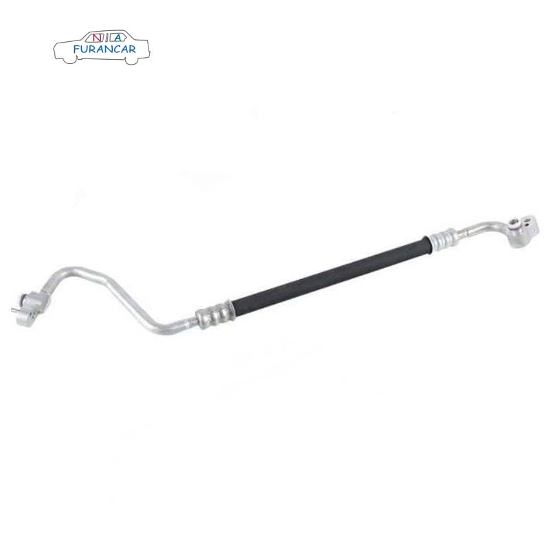
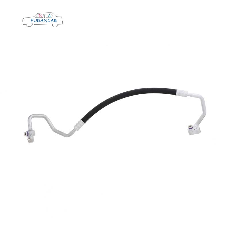
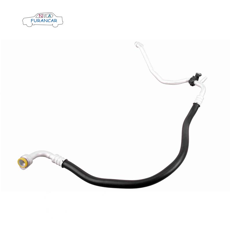
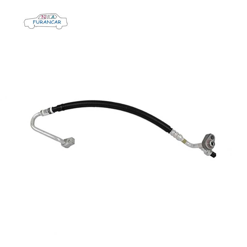
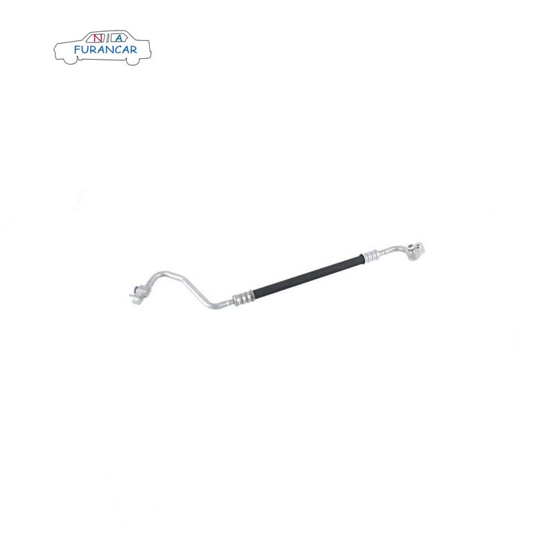
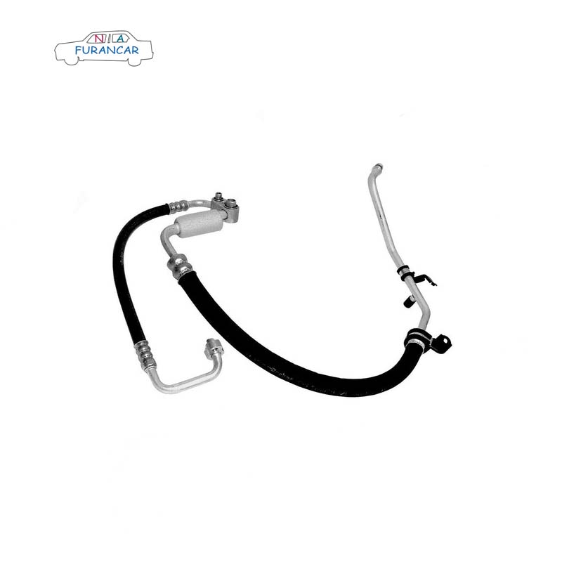
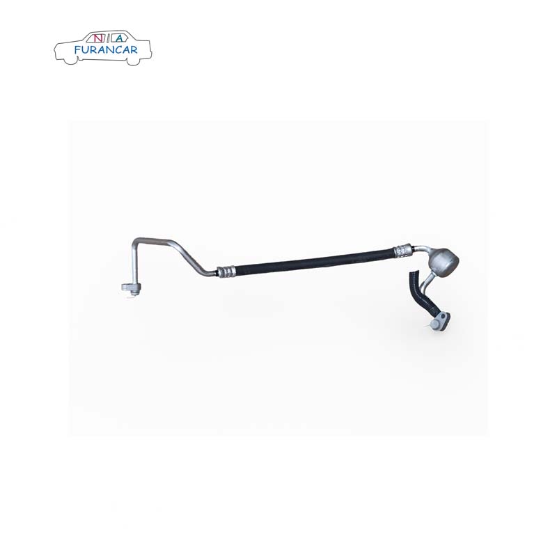
Aluminium tubing, rubber hoses and pipe fittings
These three components are joined together to connect the various parts of the air-conditioning system. Aluminium pipes and rubber hoses are joined using a crimping process; however, there may be slight variations in crimping dimensions between different pipe models and those from different manufacturers. Engine vibrations can cause damage to the pipework; the use of flexible hoses for the pipework connecting the compressor’s suction and discharge ports helps to absorb these vibrations, improve the system’s seal integrity and extend the service life of the pipework. Furthermore, some sections of pipework, such as the condenser–evaporator line, may be constructed entirely from aluminium tubing. This is primarily due to the minimal relative movement between the condenser and the evaporator.
If the design leaves little clearance between the pipework and surrounding components, or if they are already in close contact, the use of wear-resistant sleeves such as heat-shrink tubing, corrugated tubing or foam may be considered. If there is little clearance between the air-conditioning pipework and the engine exhaust manifold, thermal insulation measures must be taken, such as wrapping the hose in an aluminium foil heat-insulation sleeve.
Pipe fittings and O-rings
Pipe fittings are used to connect air-conditioning pipework and the various components of the system. Those commonly used at present include: clamp fittings, threaded fittings and quick-connect fittings.
The function of an O-ring is to seal the pipe joint. The material currently used for O-rings is HNBR.
Pipe clamp
The purpose of pipe clamps is to secure the air-conditioning pipework to the vehicle body, preventing relative movement between the two, thereby avoiding interference between the vibrating pipework and surrounding components, as well as preventing refrigerant leaks at the joints.
In addition to metal pipe clamps, plastic pipe clamps can also be used to secure air conditioning pipework. At present, there is a limited range of plastic pipe clamps used on the S-platform’s air conditioning system; however, the development of plastic pipe clamps may be considered in future, taking into account factors such as new projects and cost reduction.
When using pipe clamps, rubber liners must also be fitted to the inside of the clamps to dampen vibrations and prevent noise caused by direct contact between the aluminium pipe and the clamp.
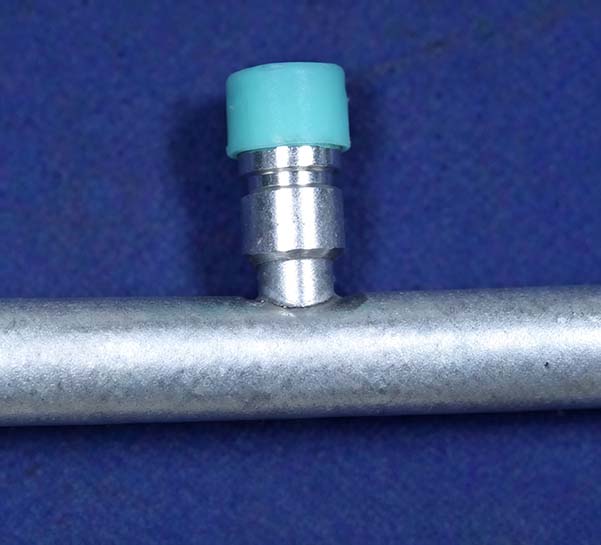
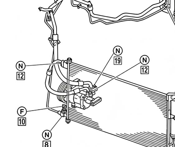
Low-pressure filling port
Their function is to charge and recover refrigerant, as well as to check the system pressure. The high-pressure charging port is usually fitted on the condenser–evaporator line, although some are fitted on the compressor–condenser line. The low-pressure charging port is fitted on the evaporator–compressor line. The appearance of the charging ports is shown in the figure. Furthermore, the charging ports must be fitted with dust caps. These are generally green in colour (although there is now a requirement to change this to blue) and are made of PP.
Pressure switches/sensors
A pressure switch/sensor is a pressure-detection component that monitors the internal pressure of a system in real time, protecting the air-conditioning system by shutting down the compressor in the event of abnormal pressure, thereby safeguarding the system. It is also used to control the speed of the cooling fan. The pressure switch/sensor is shown in the figure.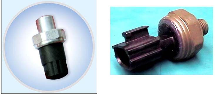
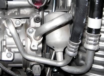
Silencer
Where design flaws in an air-conditioning system cause noise in the pipework, silencers may be fitted at the identified source of the noise to eliminate it. Silencers are typically installed on the low-pressure pipework, usually near the compressor’s suction inlet. The exact installation location must be determined through testing. It is preferable to prevent noise from occurring in the first place by optimising the system.
Gas-liquid separator
When an air-conditioning system is incorrectly sized, resulting in liquid refrigerant present in the low-pressure piping, this can cause liquid hammer in the compressor; the use of a gas-liquid separator can protect the compressor from damage. It is fitted on the evaporator–compressor line. This component is now rarely found in modern vehicles, as the problem can be avoided through proper system sizing.
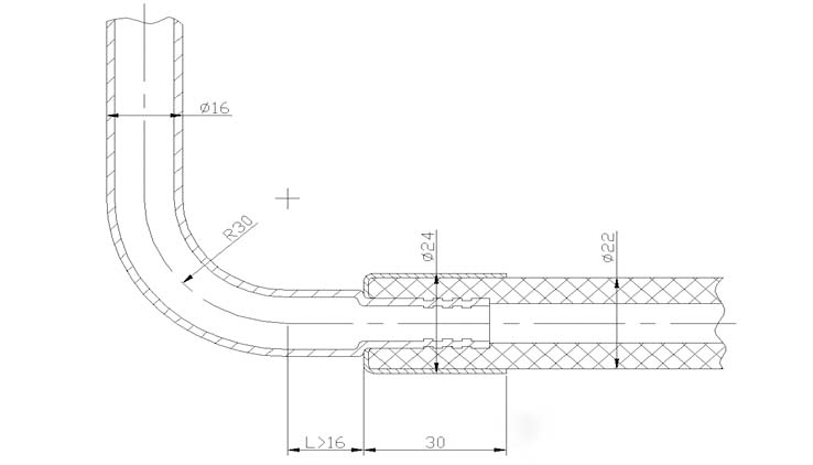
In the case of welded clamp piping, the clamp is welded to the pipe after the pipe has been bent. The head of the clamp is machined, ensuring relatively precise dimensional control. In contrast, for swaged clamp piping, the clamp (which has no head structure) is first slipped onto the pipe, and the pipe is then swaged to secure it firmly to the clamp. The torque applied to this clamp must meet the specified requirements. (Currently, the torque requirement for clamps on ¢12 and ¢16 pipes is 11 N·m, whilst for ¢10 pipes it is 6 N·m.) The pipe ends are then formed using a pipe end forming machine, a grooving machine or similar equipment. The final stage is the pipe bending process.
As piping is subject to the constraints of moulds and machinery during fabrication, we should bear the following points in mind when preparing piping data.
① The bending radii for aluminium tubes are R15/20 (¢10), R20 (¢12) and R25 (¢16). These are generally 1.5 times the outer diameter of the tube.
② The length of the shortest straight section of the pipeline centreline must be greater than 20 mm. This length is primarily limited by two factors:
1) Thickness limitations for pipe bending dies.
2) If the pipe is too short, it may come into contact with the pipe bender whilst being bent, resulting in damage or deformation.
③ The minimum distance L between the cutting point and the crimped pipe along the centreline of the aluminium tube must be greater than 16 mm; there must be no other components in the direction of the crimped pipe that could interfere with the crimping process.
④ The length of the shortest straight section at the end of the flared end is 20 mm. This value varies slightly depending on the pipe diameter. The above values should also be determined with reference to the route of the pipework.
The diagram showing the relationship between pipe bending parameters is as follows:
Pressure switches are classified as either three-position or two-position; the operating principle of a three-position pressure switch is analysed below.
1) When the refrigerant pressure is ≤ 0.12 ± 0.02 MPa, as the elastic force of the diaphragm, disc spring and upper spring exceeds the refrigerant pressure, the high- and low-pressure contacts open (OFF), causing the compressor to stop, thereby providing low-pressure protection.
2) When the refrigerant pressure reaches 0.24 MPa or above—a pressure higher than the spring force of the switch—the spring deflects, causing the high- and low-pressure contacts to close (ON), and the compressor operates normally.
3) When the refrigerant pressure reaches 3.2 MPa or above, it exceeds the elastic force of the diaphragm and the disc spring; the disc spring reverses direction to disconnect the high- and low-pressure contacts, causing the compressor to stop and thereby providing high-pressure protection.
4) Medium-pressure switch. When the refrigerant pressure exceeds 1.6 MPa, the pressure overcomes the diaphragm’s spring force, causing the diaphragm to reverse and push the shaft upwards, thereby closing the speed-change contact for the condenser fan (or radiator fan). The fan then operates at high speed, providing medium-pressure protection. When the pressure drops to 1.25 MPa, the diaphragm returns to its original position, the shaft moves downwards, the contacts open, and the condenser fan operates at low speed.
Air-conditioning ductwork layout
Air conditioning pipework serves to transport refrigerant within an air conditioning system; therefore, a well-designed layout of air conditioning pipework should incorporate the following points:
① The pipework is highly reliable, ensuring that there are no refrigerant leaks.
② Does not affect the cooling performance of the air-conditioning system—keeping the refrigerant temperature rise, pressure drop and compressor oil return rate within appropriate limits.
③ Meets NVH requirements without introducing additional vibration or noise.
④ Meet the requirements for final assembly and after-sales maintenance.
⑤ Cost optimisation.
⑥ The overall appearance should be as aesthetically pleasing as possible.
Below, we shall discuss each of these features in detail from the perspective of pipework layout.
Pipeline reliability
Based on the failure modes observed in the pipework of earlier models, we have broadly identified several main causes of pipework damage:
① Aluminium tubing or rubber hoses are worn down by surrounding components
② Aluminium or rubber hoses break as a result of engine vibrations
③ Damage caused by excessive heat at the hose connection
1) To prevent the pipework from being worn down by surrounding components, a reasonable clearance should be allowed for when routing the pipework. As a motor vehicle is a moving machine when in use, this clearance must account for both static and dynamic clearances. Static clearance refers to the gap between two objects with minimal vibration (as virtually all components vibrate whilst the vehicle is in motion), such as between the headlights and the condenser–evaporator pipework, or between the bodywork and the condenser–evaporator pipework; it is recommended that this clearance be maintained at 15 mm or more. If the clearance is too small or zero and the routing cannot be avoided, the pipes in close proximity should be wrapped in foam, heat-shrink tubing or corrugated tubing.
As the engine vibrates whilst running, dynamic clearances must be taken into account for the two pipes connected to the compressor. For example, the clearance between the compressor’s inlet and outlet hoses and the fan and drive belt. If the clearance is too small, the engine’s forward vibration may cause the air-conditioning hoses to interfere with other components; consequently, the requirements for dynamic clearance are stricter than those for static clearance, and are generally specified as 20 mm or more. As the engine tends to vibrate primarily in a fore-and-aft direction relative to the vehicle, the hoses connected to the compressor should ideally be routed perpendicular to the XZ plane.
When routing the pipework, keep it as far away as possible from the high-temperature components (exhaust pipes) in the front compartment, maintaining a distance of at least 100 mm. If it is genuinely impossible to meet this requirement, the minimum distance must be greater than 40 mm, and the surface must be wrapped in heat-insulating aluminium foil.
Pipeline vibration and noise
Vibration in air-conditioning ductwork is mainly caused by the following factors:
Methods of securing pipework and associated components;
Selection of hose types for pipework;
Noise generated by pipework layout.
These three characteristics will be discussed in turn below:
Pipe supports must be fitted with rubber gaskets to prevent rigid connections. If plastic pipe clamps are used, it is also advisable to use gaskets.
All-rubber hoses may be selected for low-pressure piping; as they are relatively flexible, they can effectively absorb vibrations and reduce noise in the pipework.
To minimise noise generated by air-conditioning pipework, the pipework should be laid as short and straight as possible; this also reduces the amount of refrigerant required.
In addition, a silencer can be fitted to the pipework; this will buffer and absorb the pressure pulses generated within the system. The positioning of the silencer is crucial and requires several trials to determine the correct location. The silencer should be installed as close as possible to the compressor end, and there should be at least 25 mm of straight pipework on either side of the silencer.