{ A/C Hose }

  • An Introduction to Automotive Air Conditioning Systems

    I. Composition of the Air Conditioning System & Introduction to Components


    Composition of the Air Conditioning System:


    Automotive air conditioning systems typically comprise the following components: compressor, condenser, receiver-drier, expansion valve, evaporator, blower fan, throttle valve, and ventilation system.


    Introduction to Air Conditioning System Components—HVAC Air Conditioning Assembly:


    The air conditioning unit employs mode selection dampers to direct cold or warm airflow to specific vents, such as footwell, face, or defrost outlets. Temperature control dampers blend cold and warm air to achieve the desired outlet temperature. The internal/external air mix damper regulates the proportion of cabin and external air, directly influencing temperature, air quality, and defrosting/demisting functionality.


    Introduction to Air Conditioning System Components—Condenser:

    Function of the condenser: to cool the refrigerant.

    The condenser integrated with a dryer, wherein a liquid receiver dryer is installed at the end of the refrigerant circuit within the condenser, facilitates simplified air conditioning system design and enhances the reliability of the refrigeration system.


    Introduction to Air Conditioning System Components—Compressor:

    The compressor serves as the ‘heart’ of the air conditioning system, analogous to the engine's role in a vehicle—it is the driving unit.
    In conventional air conditioning systems, the compressor is driven via an engine belt.
    The compressor must exclusively draw in and expel gaseous refrigerant.
    Its internal mechanism contains numerous moving parts, necessitating sufficient lubricating oil to lubricate these components.


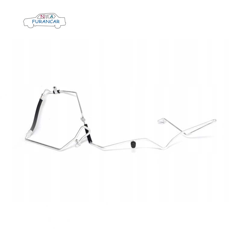
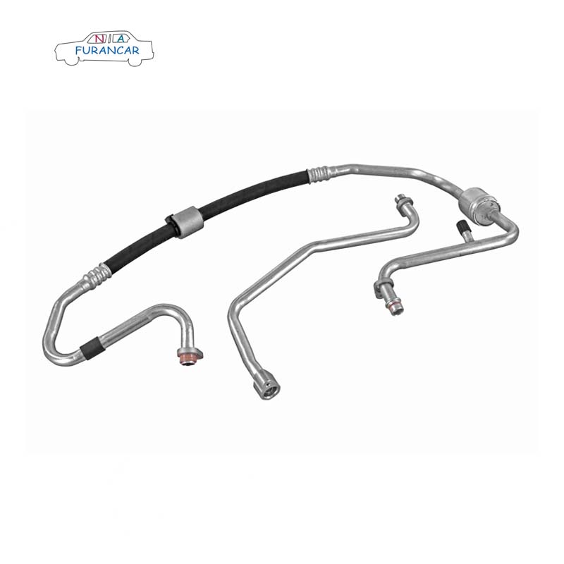
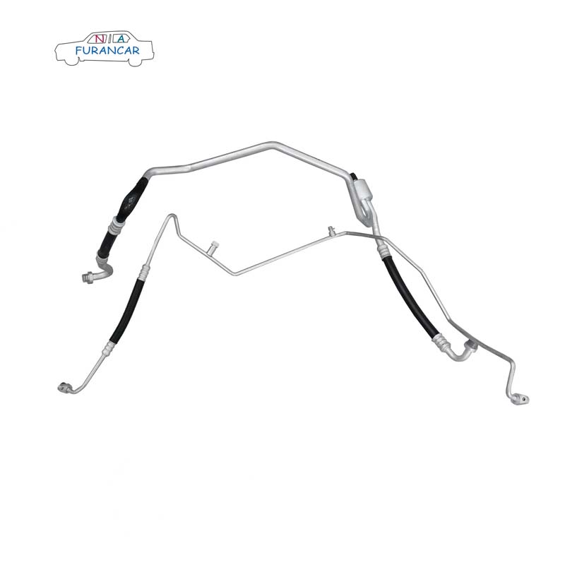
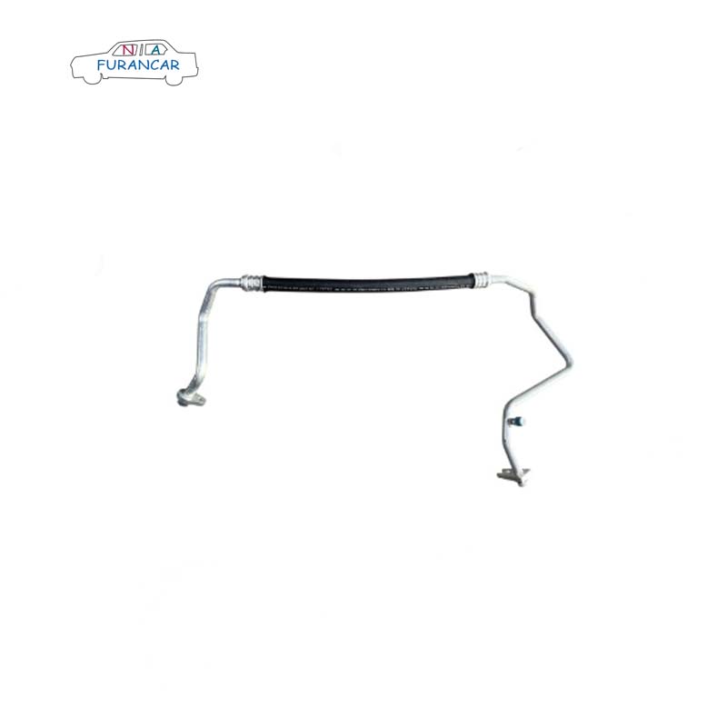
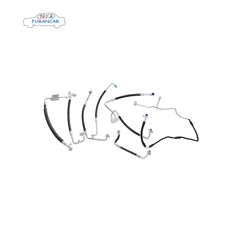
    Introduction to Air Conditioning System Components—Air Conditioning Piping:

    The air conditioning piping system comprises key components such as aluminium tubing, flexible hoses, and pipe fittings, which collectively connect all elements of the air conditioning system. Aluminium tubing and flexible hoses are tightly joined via crimping techniques, though minor variations in crimp dimensions may exist between different models and manufacturers. To mitigate potential damage from engine vibration, flexible rubber hoses are employed for the lines connecting the compressor's suction and discharge ports. Their flexible design effectively absorbs vibrations, enhances system sealing integrity, and extends the service life of the piping. Many manufacturers have also developed nylon air conditioning hoses, which are utilised in mass-produced vehicle models.

    II. Refrigeration Principles of Air Conditioning Systems


    The operational principle of refrigeration systems relies upon the continuous vaporisation and liquefaction of refrigerant. The entire refrigeration cycle comprises four distinct operational stages: compression, condensation and heat release, throttling, and evaporation. During compression, the low-temperature, low-pressure refrigerant gas processed by the evaporator is compressed by the compressor into a high-temperature, high-pressure gas, which is then delivered to the condenser. During the condensation and heat release stage, the high-temperature, high-pressure refrigerant gas gradually condenses into a liquid while releasing heat. The subsequent throttling process, via the expansion valve, transforms the refrigerant from a high-pressure to a low-pressure state. Finally, the evaporation process occurs within the evaporator, where the refrigerant absorbs a significant amount of heat before re-entering the compressor, thereby achieving the cooling of the vehicle's interior.


    III. Precautions for Air Conditioning Refrigerant Pipe Assembly


    When installing air conditioning pipework and connecting components, the method of fitting and tightening joints is critical.
    When removing pipe plugs, first inspect the O-ring for integrity and apply lubricant evenly to its sealing surface. For threaded pipe joints, also apply lubricant evenly to the external threads. When applying lubricant, observe the following points: 
    The lubricant applied must be compressor-grade lubricant, PAG or equivalent grade.
    Lubricate threaded sections to prevent seizing after tightening.
    To prevent moisture absorption, promptly reseal lubricant containers after use.
    To maintain internal cleanliness of system components such as piping, remove plugs only immediately prior to installation. Refit promptly; do not leave exposed to air for extended periods.  
    Clamp-type joint connection: Insert the lubricated clamp plate's blind hole vertically through the double-ended stud. Simultaneously insert the clamp joint vertically into the corresponding mounting hole. Avoid tilting during insertion to prevent O-ring damage. Once seated with parallel faces, hand-tighten the nut until resistance is encountered. Subsequently, use a torque ratchet or wrench to tighten the bolt to specification, marking the tightened position. The tightening torque for M8 nuts is 15–20 N·m; for expansion valve nuts (M6), it is 6–10 N·m. 
    Threaded joint connection. Insert the lubricated sealing ring end into the threaded joint end. Align and insert vertically until the front face of the plug head contacts the threaded joint. Hand-tighten the nut, then secure the threaded joint end with an open-end spanner. Tighten the nut end using a torque wrench, marking the tightened position (see figure below). Tightening torque specifications: High-pressure pipe fitting (M16×1.5 threaded joint): 12–15 N·m Low-pressure pipe fitting (M24×1.5 threaded joint): 30–35 N·m.

    Note: When tightening threaded joints, it is essential to use two spanners simultaneously to avoid deformation of the pipework.


    Connection of dual clamp joints. First position the end of the high-pressure clamp within the fork slot of the low-pressure clamp. Align and push the compressor interface in parallel. Once the clamps are flattened, inspect the O-ring position for misalignment or extrusion. Hand-tighten the bolts until resistance is encountered, then use a torque ratchet or wrench to tighten to specification, marking the tightened position (see figure below). The tightening torque for the compressor tail bolts (M10×1.25×35) is 20–30 N·m.


    Supplementary Notes on Air Conditioning Pipe Installation:

    Minor damage to O-rings during pipe installation may compromise sealing integrity, leading to refrigerant leakage.
    Following installation, verify that pipes do not interfere with or exhibit free movement relative to surrounding vehicle components. Address any friction or interference promptly through adjustment, and secure pipes prone to free movement with appropriate fastenings.
    Moving components such as the engine throttle cable and oil dipstick must never be bundled together with air conditioning piping. This prevents abrasion of the air conditioning lines, which could lead to refrigerant leakage.

  • Analysis of Automotive Thermal Management Issues in the Assembly and Design of Air Conditioning Pipes

    Design must take into account not only manufacturing processes but also the ease of assembly for the OEM. During the pilot production phase for a new automotive model, frequent assembly difficulties arose with the air conditioning refrigeration piping, resulting in substantial costs for subsequent design modifications. By incorporating concurrent engineering into the final assembly process, virtual assembly analysis and design constraints were applied during the development of the air conditioning refrigeration piping. This effectively reduced production costs during the manufacturing process and improved production efficiency. This paper briefly outlines the assembly and design issues encountered in the synchronous engineering analysis of air conditioning refrigeration piping, along with their solutions, and provides valuable guidance for the development of air conditioning refrigeration piping in new vehicle models.

    I. Introduction to Synchronised Engineering for Final Assembly


    Synchronised Engineering (SE) for final assembly is a process in which final assembly processes are integrated into the design and development phase of vehicle development. It primarily involves conducting process analyses of assembly digital models, production lines, equipment and assembly processes, and provides feasible process design changes to support the design. Its primary objective is to review issues in product design during the drawing design and digital model generation stages, taking effective measures in advance to address potential problems that may arise during process implementation, thereby ensuring the new vehicle model is production-feasible and compatible with equipment and tools.


    II.  Air Conditioning Piping Assembly and Design 


    1. Composition of the Front Engine Compartment Air Conditioning Refrigerant Piping

    The air conditioning refrigerant piping primarily comprises the air conditioning high- and low-pressure pipe assembly, air conditioning exhaust pipe assembly II, air conditioning exhaust pipe assembly I (which may be combined with air conditioning exhaust pipe assembly II, depending on assembly considerations), air conditioning low-pressure pipe assembly I, and air conditioning high-pressure pipe assembly I (which may be combined with the air conditioning high- and low-pressure pipe assembly, depending on assembly considerations).

    2. Issues with the design and assembly of the air conditioning refrigerant piping

    (1) At the connection between the high- and low-pressure pipe assembly and the HVAC expansion valve, the foam padding on the clamps attached to the pipes is too thick and too rigid, causing excessive interference with the front panel and making the piping difficult to fit.


    (2) The air conditioning high- and low-pressure pipe assembly comes with its own mounting brackets (secured to the engine compartment side panels and longitudinal beams). The cut-outs are circular, but the allowance for offset in the X-direction is too small; due to the combination of fitting accuracy and cumulative tolerances, the bolt holes cannot be aligned.


    (3) The air conditioning refrigerant lines are connected using bolts and nuts; during prototyping, there is insufficient working space for tightening tools (such as a cordless impact wrench). The interference persists even when a shorter socket is used.


    (4) It is not possible to apply refrigeration oil to the clamps during assembly of the pipe joints, and refrigerant leaks occur once assembly is complete. There is no flexible hose section connecting the high- and low-pressure pipe assemblies to the high-pressure pipe assembly; the rigid pipes are difficult to connect and prone to deformation.


    (5) The piping layout is not sufficiently well-designed, leading to frequent issues such as abnormal noises and poor assembly ergonomics; for example, the piping does not run close enough to the engine compartment, and the air conditioning filling port is positioned too low to allow for refilling.

    3. Design Constraints for Air Conditioning Refrigerant Piping

    Design constraints are guidelines derived from a compilation of common issues encountered during the introduction of new vehicle models and the prototyping process; they are intended to identify areas requiring improvement in subsequent product designs. In response to the assembly issues outlined above, the following design constraints have been established.


    (1) The foam used in the clamping plate at the connection between the air conditioning high- and low-pressure pipe assembly and the HVAC expansion valve should be made of PUR material, with a thickness preferably less than 15 mm.


    (2) With the exception of the primary locating holes, all holes in the brackets on the air conditioning high- and low-pressure pipe assemblies shall be elliptical in the X-direction (e.g. 8×10, depending on the bolt specification), to accommodate cumulative tolerances. A rotational restraint mechanism (such as a locking clip) must be provided at the point where the bracket connects to the vehicle body to prevent the bracket from rotating when the bolts are tightened, which could cause deformation of the piping. The brackets for the air conditioning pipes must be designed to be mounted on the rigid pipe sections to avoid scratching the flexible hoses.


    (3) When designing the system, consideration must be given to the working space required for operating pipe connection fastening tools. When using an elbow gun, the distance between the rivet head and the end of the stud must be greater than 85 mm; when using a straight gun, the distance between the rivet head and the end of the stud must be 40 mm. 


     (4) The male end of pipe fittings must face upwards in the Z-direction (no requirement for the X-direction) to facilitate the application of refrigeration oil. Rigid pipes must not be connected directly to one another; a flexible hose must be used as an intermediate connection, and the joint must be properly sealed, for example by fitting a sealing gasket. 


     (5) Above the high- and low-pressure filling ports of the air conditioning high- and low-pressure pipe assemblies, there must be a clear space with a diameter of 50 mm and a height of 250 mm. Furthermore, the spacing between the high- and low-pressure filling ports must be reasonable (depending on the size of the filling nozzle).

    III. Conclusion     


    This paper summarises the common issues encountered during the final assembly of the refrigeration piping system for a particular automotive air conditioning unit. By incorporating SA constraints into the design phase through concurrent engineering during the early stages of new model introduction, this approach has helped to minimise design shortcomings, optimise the manufacturability of the final assembly process, and reduce production costs for the company. Furthermore, it provides valuable guidance for the development of refrigeration piping systems for new vehicle models.