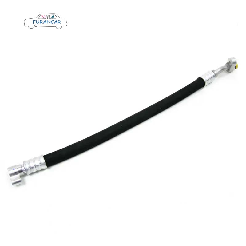
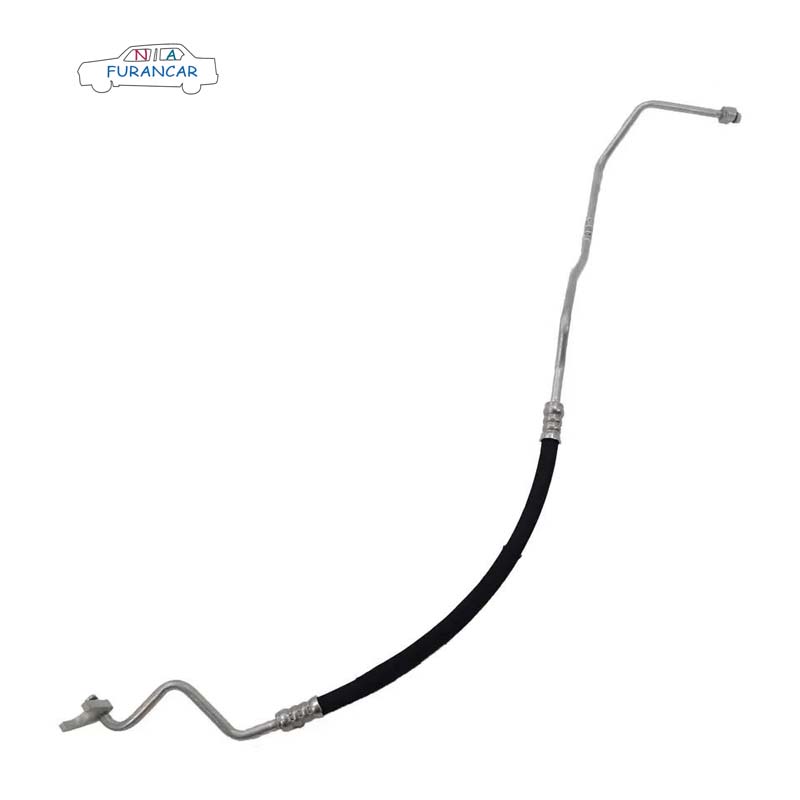
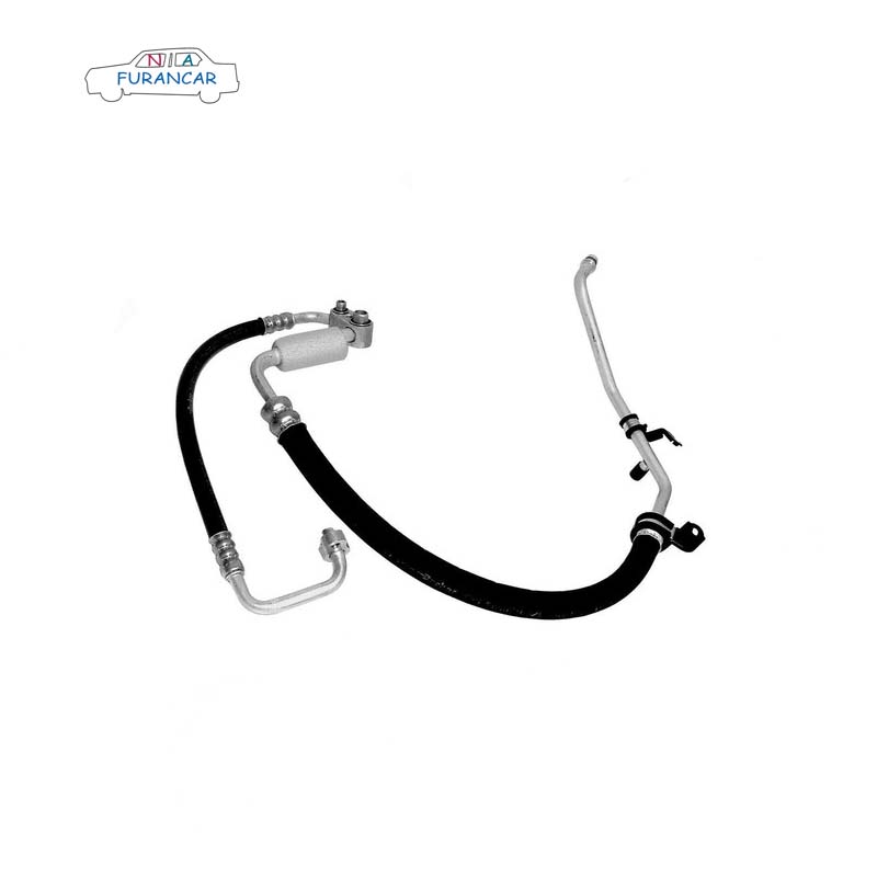
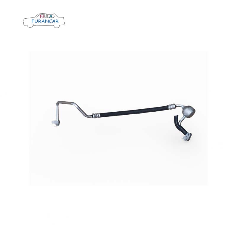
{ AC Hose }

  • Auto air conditioning pipework

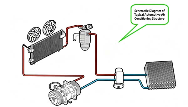
    Air conditioning piping connects the four major components of the system—the compressor, condenser, evaporator and expansion valve—to form a closed system, within which the refrigerant is stored or circulates. When the air conditioning system is in operation, the refrigerant circulates continuously, exchanging heat with the outside environment to achieve the cooling function. To ensure the refrigerant transfers heat smoothly and efficiently, the routing of the pipework must be well-designed, facilitating both assembly and disassembly, whilst also being easy to manufacture and cost-effective.


    Aluminium tubing, rubber hoses and pipe fittings

    These three components are joined together to connect the various parts of the air-conditioning system. Aluminium pipes and rubber hoses are joined using a crimping process; however, there may be slight variations in crimping dimensions between different pipe models and those from different manufacturers. Engine vibrations can cause damage to the pipework; the use of flexible hoses for the pipework connecting the compressor’s suction and discharge ports helps to absorb these vibrations, improve the system’s seal integrity and extend the service life of the pipework. Furthermore, some sections of pipework, such as the condenser–evaporator line, may be constructed entirely from aluminium tubing. This is primarily due to the minimal relative movement between the condenser and the evaporator.

    If the design leaves little clearance between the pipework and surrounding components, or if they are already in close contact, the use of wear-resistant sleeves such as heat-shrink tubing, corrugated tubing or foam may be considered. If there is little clearance between the air-conditioning pipework and the engine exhaust manifold, thermal insulation measures must be taken, such as wrapping the hose in an aluminium foil heat-insulation sleeve. 


    Pipe fittings and O-rings

    Pipe fittings are used to connect air-conditioning pipework and the various components of the system. Those commonly used at present include: clamp fittings, threaded fittings and quick-connect fittings.

    The function of an O-ring is to seal the pipe joint. The material currently used for O-rings is HNBR.


    Pipe clamp

    The purpose of pipe clamps is to secure the air-conditioning pipework to the vehicle body, preventing relative movement between the two, thereby avoiding interference between the vibrating pipework and surrounding components, as well as preventing refrigerant leaks at the joints.

    In addition to metal pipe clamps, plastic pipe clamps can also be used to secure air conditioning pipework. At present, there is a limited range of plastic pipe clamps used on the S-platform’s air conditioning system; however, the development of plastic pipe clamps may be considered in future, taking into account factors such as new projects and cost reduction.

    When using pipe clamps, rubber liners must also be fitted to the inside of the clamps to dampen vibrations and prevent noise caused by direct contact between the aluminium pipe and the clamp.


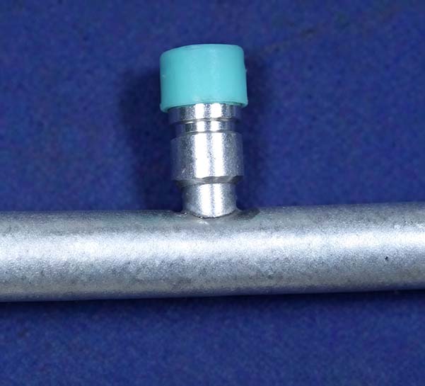
    Low-pressure filling port

    Their function is to charge and recover refrigerant, as well as to check the system pressure. The high-pressure charging port is usually fitted on the condenser–evaporator line, although some are fitted on the compressor–condenser line. The low-pressure charging port is fitted on the evaporator–compressor line. The appearance of the charging ports is shown in the figure. Furthermore, the charging ports must be fitted with dust caps. These are generally green in colour (although there is now a requirement to change this to blue) and are made of PP.

    Pressure switches/sensors

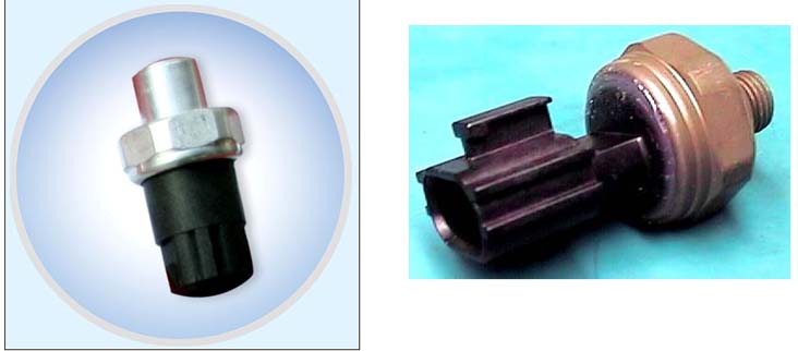
    A pressure switch/sensor is a pressure-detection component that monitors the internal pressure of a system in real time, protecting the air-conditioning system by shutting down the compressor in the event of abnormal pressure, thereby safeguarding the system. It is also used to control the speed of the cooling fan. The pressure switch/sensor is shown in the figure.

    Silencer

    Where design flaws in an air-conditioning system cause noise in the pipework, silencers may be fitted at the identified source of the noise to eliminate it. Silencers are typically installed on the low-pressure pipework, usually near the compressor’s suction inlet. The exact installation location must be determined through testing. It is preferable to prevent noise from occurring in the first place by optimising the system.
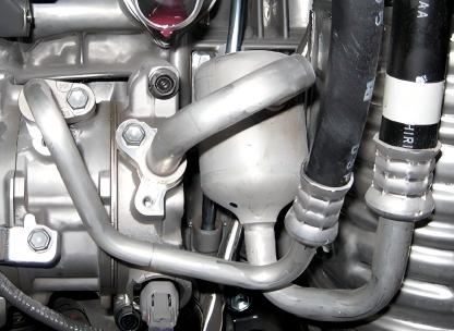

    Gas-liquid separator

    When an air-conditioning system is incorrectly sized, resulting in liquid refrigerant present in the low-pressure piping, this can cause liquid hammer in the compressor; the use of a gas-liquid separator can protect the compressor from damage. It is fitted on the evaporator–compressor line. This component is now rarely found in modern vehicles, as the problem can be avoided through proper system sizing.

    In the case of welded clamp piping, the clamp is welded to the pipe after the pipe has been bent. The head of the clamp is machined, ensuring relatively precise dimensional control. In contrast, for swaged clamp piping, the clamp (which has no head structure) is first slipped onto the pipe, and the pipe is then swaged to secure it firmly to the clamp. The torque applied to this clamp must meet the specified requirements. (Currently, the torque requirement for clamps on ¢12 and ¢16 pipes is 11 N·m, whilst for ¢10 pipes it is 6 N·m.) The pipe ends are then formed using a pipe end forming machine, a grooving machine or similar equipment. The final stage is the pipe bending process.

    As piping is subject to the constraints of moulds and machinery during fabrication, we should bear the following points in mind when preparing piping data.


    ① The bending radii for aluminium tubes are R15/20 (¢10), R20 (¢12) and R25 (¢16). These are generally 1.5 times the outer diameter of the tube.

    ② The length of the shortest straight section of the pipeline centreline must be greater than 20 mm. This length is primarily limited by two factors:

    1) Thickness limitations for pipe bending dies.

    2) If the pipe is too short, it may come into contact with the pipe bender whilst being bent, resulting in damage or deformation.

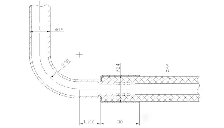
    ③ The minimum distance L between the cutting point and the crimped pipe along the centreline of the aluminium tube must be greater than 16 mm; there must be no other components in the direction of the crimped pipe that could interfere with the crimping process.

    ④ The length of the shortest straight section at the end of the flared end is 20 mm. This value varies slightly depending on the pipe diameter. The above values should also be determined with reference to the route of the pipework.

    The diagram showing the relationship between pipe bending parameters is as follows:

    Pressure switches are classified as either three-position or two-position; the operating principle of a three-position pressure switch is analysed below.

    1) When the refrigerant pressure is ≤ 0.12 ± 0.02 MPa, as the elastic force of the diaphragm, disc spring and upper spring exceeds the refrigerant pressure, the high- and low-pressure contacts open (OFF), causing the compressor to stop, thereby providing low-pressure protection.

    2) When the refrigerant pressure reaches 0.24 MPa or above—a pressure higher than the spring force of the switch—the spring deflects, causing the high- and low-pressure contacts to close (ON), and the compressor operates normally.

    3) When the refrigerant pressure reaches 3.2 MPa or above, it exceeds the elastic force of the diaphragm and the disc spring; the disc spring reverses direction to disconnect the high- and low-pressure contacts, causing the compressor to stop and thereby providing high-pressure protection.

    4) Medium-pressure switch. When the refrigerant pressure exceeds 1.6 MPa, the pressure overcomes the diaphragm’s spring force, causing the diaphragm to reverse and push the shaft upwards, thereby closing the speed-change contact for the condenser fan (or radiator fan). The fan then operates at high speed, providing medium-pressure protection. When the pressure drops to 1.25 MPa, the diaphragm returns to its original position, the shaft moves downwards, the contacts open, and the condenser fan operates at low speed.


    Air-conditioning ductwork layout

    Air conditioning pipework serves to transport refrigerant within an air conditioning system; therefore, a well-designed layout of air conditioning pipework should incorporate the following points:

    ① The pipework is highly reliable, ensuring that there are no refrigerant leaks.

    ② Does not affect the cooling performance of the air-conditioning system—keeping the refrigerant temperature rise, pressure drop and compressor oil return rate within appropriate limits.

    ③ Meets NVH requirements without introducing additional vibration or noise.

    ④ Meet the requirements for final assembly and after-sales maintenance.

    ⑤ Cost optimisation.

    ⑥ The overall appearance should be as aesthetically pleasing as possible.

    Below, we shall discuss each of these features in detail from the perspective of pipework layout.


    Pipeline reliability

    Based on the failure modes observed in the pipework of earlier models, we have broadly identified several main causes of pipework damage:

    ① Aluminium tubing or rubber hoses are worn down by surrounding components

    ② Aluminium or rubber hoses break as a result of engine vibrations

    ③ Damage caused by excessive heat at the hose connection

    1) To prevent the pipework from being worn down by surrounding components, a reasonable clearance should be allowed for when routing the pipework. As a motor vehicle is a moving machine when in use, this clearance must account for both static and dynamic clearances. Static clearance refers to the gap between two objects with minimal vibration (as virtually all components vibrate whilst the vehicle is in motion), such as between the headlights and the condenser–evaporator pipework, or between the bodywork and the condenser–evaporator pipework; it is recommended that this clearance be maintained at 15 mm or more. If the clearance is too small or zero and the routing cannot be avoided, the pipes in close proximity should be wrapped in foam, heat-shrink tubing or corrugated tubing.

    As the engine vibrates whilst running, dynamic clearances must be taken into account for the two pipes connected to the compressor. For example, the clearance between the compressor’s inlet and outlet hoses and the fan and drive belt. If the clearance is too small, the engine’s forward vibration may cause the air-conditioning hoses to interfere with other components; consequently, the requirements for dynamic clearance are stricter than those for static clearance, and are generally specified as 20 mm or more. As the engine tends to vibrate primarily in a fore-and-aft direction relative to the vehicle, the hoses connected to the compressor should ideally be routed perpendicular to the XZ plane.
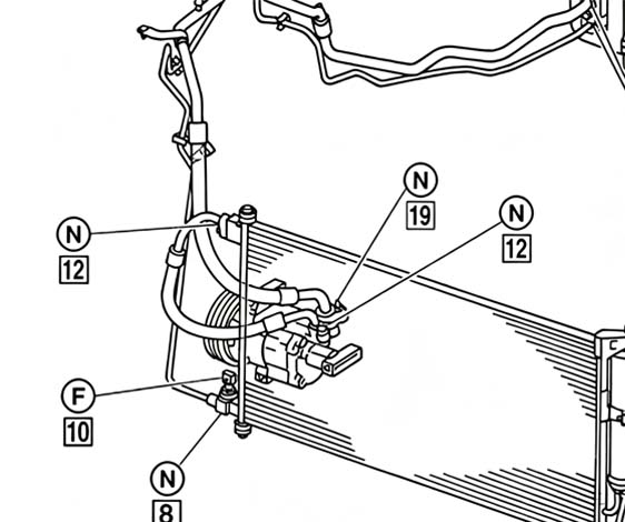

    When routing the pipework, keep it as far away as possible from the high-temperature components (exhaust pipes) in the front compartment, maintaining a distance of at least 100 mm. If it is genuinely impossible to meet this requirement, the minimum distance must be greater than 40 mm, and the surface must be wrapped in heat-insulating aluminium foil.


    Pipeline vibration and noise

    Vibration in air-conditioning ductwork is mainly caused by the following factors:

    Methods of securing pipework and associated components; 

    Selection of hose types for pipework; 

    Noise generated by pipework layout.


    These three characteristics will be discussed in turn below:

    Pipe supports must be fitted with rubber gaskets to prevent rigid connections. If plastic pipe clamps are used, it is also advisable to use gaskets.

    All-rubber hoses may be selected for low-pressure piping; as they are relatively flexible, they can effectively absorb vibrations and reduce noise in the pipework.

    To minimise noise generated by air-conditioning pipework, the pipework should be laid as short and straight as possible; this also reduces the amount of refrigerant required.

    In addition, a silencer can be fitted to the pipework; this will buffer and absorb the pressure pulses generated within the system. The positioning of the silencer is crucial and requires several trials to determine the correct location. The silencer should be installed as close as possible to the compressor end, and there should be at least 25 mm of straight pipework on either side of the silencer.
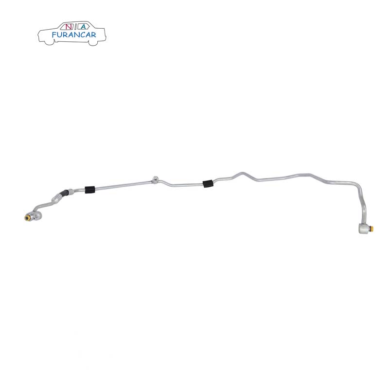
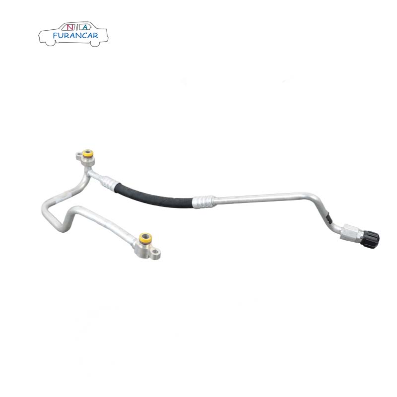
  • Design Requirements and Failure Mode Analysis for Automotive Air Conditioning Piping

    |

    With the rapid development of the automotive industry, automotive air-conditioning systems have significantly enhanced driving and passenger comfort, and there is growing emphasis on their functional requirements and technological innovation. The performance of the air-conditioning system relies on the connections within the piping system, such as high-pressure and low-pressure lines; consequently, the design requirements for air-conditioning piping are of particular importance. This paper explores the technical development process of air conditioning piping by providing a detailed overview of the composition, operating principles, piping design, manufacturing processes and testing requirements of automotive air conditioning systems. Furthermore, it analyses common failure modes in automotive air conditioning piping and proposes corresponding corrective measures and maintenance recommendations, thereby providing a reference for future project development and design.


    Introduction

    As a vital component of a vehicle’s interior, the air conditioning system enhances the comfort of both driver and passengers and plays a significant role in the vehicle’s overall performance. The air conditioning piping, as the core component of this system, acts much like the ‘blood vessels of the human body’, connecting key components such as the compressor, condenser, evaporator and expansion valve to form a closed-loop system. This ensures the orderly flow of refrigerant within the system, thereby enabling the air conditioning system to provide both cooling and heating functions.

    With the rapid development of the Chinese automotive market, consumers are placing ever-higher demands on the performance, reliability and energy efficiency of vehicle air-conditioning systems. The design, manufacture and maintenance of vehicle air-conditioning piping systems present numerous challenges, necessitating continuous innovation and optimisation. A thorough examination of the relevant technologies and solutions for vehicle air-conditioning piping systems is of significant practical importance for enhancing the overall performance of these systems, reducing energy consumption, minimising failure rates and improving the user experience.

    912000310


    An Overview of Automotive Air Conditioning Systems

    1. Components and Operating Principles of the Car Air Conditioning System

    A vehicle’s air conditioning system primarily consists of a compressor, cooling fan, condenser, blower, desiccant drier, air conditioning piping, evaporator, expansion valve and refrigerant. In new energy vehicles equipped with liquid-cooled battery packs, a radiator is also required.


    The primary function of a vehicle air conditioning system is to provide cooling and heating, ensuring a comfortable environment for passengers inside the vehicle. The cooling process of the air conditioning system primarily comprises compression, condensation, throttling, evaporation and circulation. Firstly, the compressor compresses the low-temperature, low-pressure gaseous refrigerant into a high-temperature, high-pressure gas, which is then fed into the condenser. Secondly, within the condenser, the refrigerant is cooled and liquefied, transforming into a medium-temperature, high-pressure liquid, before flowing into the receiver-drier for storage and drying. Next, after passing through the expansion valve where pressure is reduced, the refrigerant becomes a low-temperature, low-pressure liquid and enters the evaporator. Finally, within the evaporator, the refrigerant boils and absorbs heat, cooling the air flowing through it and thereby achieving the cooling effect; the gaseous refrigerant is then drawn back into the compressor, completing a cycle. During the cooling process, the air conditioning piping provides a flow path for the refrigerant.


    The heating mechanisms in automotive air conditioning systems primarily involve utilising engine waste heat and employing independent heating units. Traditional petrol and diesel vehicles mainly rely on the heat generated by the engine, whereas new energy vehicles utilise PTC thermistors for heating.


    2. Functions and classifications of automotive air conditioning piping

    Air conditioning piping plays a crucial role in automotive air conditioning systems by connecting various components and conveying refrigerant, ensuring the smooth circulation of refrigerant within the system. Automotive air conditioning piping assemblies can be categorised into compressor piping assemblies, condenser piping, heater core piping and ventilation system piping, amongst others. Automotive air conditioning piping can be classified by material into copper tubing, aluminium tubing and rubber hoses; by pressure into high-pressure and low-pressure lines; and, based on the state of the refrigerant during the cycle, into gas-phase and liquid-phase lines.


    As aluminium tubing is lightweight, it plays a positive role in automotive weight reduction design; consequently, aluminium tubing is now widely used in automotive air conditioning systems. Automotive air conditioning piping systems primarily consist of aluminium tubing, fittings (clamps, connectors, nuts, etc.), flexible hoses, corrugated hoses, aluminium sleeves, charging ports, O-rings, pressure switches and plastic caps. To ensure that the air conditioning refrigerant does not leak, the quality of the piping fitting design is of paramount importance. Fittings in automotive air conditioning piping are key to ensuring airtightness; the main types of fittings currently in use are threaded connections and clamp connections.


    Threaded connections involve joining aluminium tubes to one another, or aluminium tubes to other components, using nuts and external threads. Clamp connections use clamps and bolts to secure pipe joints tightly together, ensuring both sealing and stability. When tightening threads, the hose may become twisted; hoses subjected to torsional shear stress are prone to premature fatigue failure, and this torsional force also tends to cause the joint to loosen. Consequently, clamping structures are now preferred for air conditioning piping.

    64509181882


    Design Requirements for Automotive Air Conditioning Piping

    1. Requirements for the installation and routing of automotive air conditioning pipes

    Automotive air conditioning pipework is subject to vibration, impact and temperature fluctuations whilst the vehicle is in motion; therefore, the secure installation of the pipework is of paramount importance. Proper securing prevents loosening, wear and leakage, ensuring the normal operation and long-term reliability of the air conditioning system. Where two pipes run parallel to one another, welded nut holes are typically designed at suitable positions on the front bulkhead outer panel, and multi-pipe clamps are used to secure the pipework, with fixing points generally spaced at intervals of 300 mm. At the same time, cable ties are often used to assist with securing the lines. For rigid pipes, the distance between two fixing points should be between 100 and 400 mm to prevent excessive vibration caused by overly long sections. The addition of fixing points on flexible hoses should be minimised to reduce stress and wear on the hoses. Additional fixing points should be added at bends to ensure stability at these points.


    When designing air conditioning ductwork, a series of layout requirements must be met. The angle of bends in rigid ducting should be greater than 90°; the bend radius should be 1.5 to 2 times the diameter of the duct; the minimum straight section following a bend should be no less than 15 mm; and the connection between flexible and rigid ducting should be greater than 35 mm. The clearance between the ductwork and surrounding components should be no less than 6 mm to prevent wear caused by contact between the ductwork and surrounding components.


    3. Testing requirements for air conditioning ductwork

    To prevent refrigerant leaks during the circulation process, automotive air-conditioning systems must meet stringent airtightness requirements; during the design and development phase, numerous tests must be conducted to verify the soundness of the design, if the test is passed, this indicates that the airtightness of the piping meets the requirements.

    64531504536


    Failure Mode Analysis of Automotive Air Conditioning Piping

    According to relevant statistics, faults in air conditioning systems caused by incorrect refrigerant charging rank as the most common issue, with leaks at the joint between the evaporator outlet pipe and the compressor suction pipe accounting for as much as 90% of these cases. Consequently, the primary failure mode in automotive air conditioning piping is refrigerant leakage at the joints, which is attributed to the following specific causes.


    1. Ageing of pipework

    After prolonged use, the rubber components of a car’s air conditioning system gradually age, harden and crack, leading to refrigerant leaks through these fissures. As the air conditioning pipes are mainly located in the engine compartment, where they are constantly exposed to high temperatures and vibrations, the ageing process is accelerated.


    2. Loose connection

    The joints in the air conditioning pipework may become loose whilst the vehicle is in motion, due to vibrations and other factors. Should a joint become loose, the seal will be compromised, making it likely for refrigerant to leak from the joint.


    3. Component failure

    Components in an air-conditioning system, such as the compressor, condenser and evaporator, can also cause refrigerant leaks if their internal seals are damaged or if the components themselves develop defects such as cracks or pinholes. For example, a damaged shaft seal on the compressor can cause refrigerant to leak from the seal into the external environment.


    4. Traumatic injury

    Whilst the vehicle is in motion, the air conditioning pipes may be subjected to external forces such as impacts from stones or scrapes from branches, which can cause damage to the pipes and result in refrigerant leaks. Furthermore, improper handling during vehicle maintenance and servicing may also damage the air conditioning pipes.


    5. Abnormal pressure

    If the pressure in an air-conditioning system is too high or too low, it can damage the pipework and components, increasing the risk of refrigerant leaks. For example, if non-condensable gases such as air enter the refrigeration system, this can cause the system pressure to rise excessively, leading to the failure of seals in the pipework or components and resulting in refrigerant leaks.


    To prevent refrigerant leaks caused by the above factors, the following points should be observed. Firstly, during vehicle use, the exterior of the air conditioning piping should be inspected regularly for signs of ageing, cracking or damage, particularly at bends in the piping and in areas close to heat sources such as the engine. Secondly, the pipe joints should be checked frequently for looseness or leaks; this can be done by applying soapy water to check for the formation of bubbles, which indicates a leak. Furthermore, the operational status of all components within the air conditioning system should be checked regularly, such as whether the compressor is running normally and whether there is abnormal frost build-up on the condenser or evaporator. Finally, the air conditioning system should be used correctly in accordance with the vehicle’s owner’s manual. Avoid running the air conditioning for extended periods whilst the engine is not running, as this places an unnecessary strain on the compressor. Finally, during vehicle servicing, ensure the air conditioning system is properly maintained. This includes replacing the air filter to keep the system clean, preventing dust and other contaminants from entering the system, which could impair cooling performance and damage components. Furthermore, during vehicle repairs, take care to avoid damaging the air conditioning pipes and components. If it is necessary to remove the air conditioning pipes, follow standard operating procedures; after removal, protect the pipe joints and other areas to prevent foreign objects from entering.

    A1698301715


    Conclusion

    This paper explores the technical development process of air conditioning piping by providing a detailed overview of the composition, operating principles, piping design, manufacturing processes and testing requirements of automotive air conditioning systems. Furthermore, by analysing and addressing leakage issues in air conditioning pipe joints, it proposes corresponding corrective measures and maintenance recommendations, thereby providing a reference for future project development and design. The technical development of air conditioning piping and the resolution of leakage issues not only affect the performance of the air conditioning system but also directly impact passenger comfort and the overall quality of the vehicle. Therefore, the design, fabrication and maintenance of air conditioning piping should be given due attention.

  • Is your car’s air conditioning pipe leaking? Find out what causes this problem

    |

    Car air conditioning, an indispensable ‘must-have’ for driving in the sweltering summer heat, provides us with a comfortable environment whilst on the road.

    If the compressor is the heart of the air-conditioning system, then the vehicle’s air-conditioning piping is its circulatory system, connecting the various air-conditioning components scattered throughout the vehicle to form a complete and efficiently functioning air-conditioning system.


    Car air conditioning pipework typically consists of aluminium pipes, flexible hoses and other fittings.


    Unlike other car components, air conditioning pipes do not need to be replaced very often, which means they are easily overlooked; as a result, some car owners fail to notice leaks in the pipework in good time.

    Generally speaking, there are typically two causes of leaks in air conditioning pipes: 

    •  A blockage in the air conditioning system’s circuit, leading to prolonged high-temperature and high-pressure conditions between the compressor and the condenser, causing the PA layer on the inner wall of the rubber pipe to age and crack.  
    •  During the crimping of the aluminium sleeve, if the pipe is not positioned correctly, gas can escape from the top of the crimped area into the braided layer, penetrating the rubber layer and causing a general leak. This phenomenon is also known as a gas leak.

    Although air conditioning hoses do not need to be replaced very often, over time they can accumulate dirt and grime that is difficult to clean out; it is therefore advisable to fit new ones. When replacing air conditioning hoses, be sure to choose products of guaranteed quality to avoid system faults caused by substandard hoses.